| Welcome to a...
|
|||||||||
|
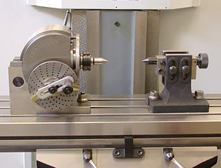
Spring, 2012 - This is a site describing the build of an electronic indexing head, which I am going to call a Step Indexer. First, a word about what that is... An indexing head (aka a dividing head or a spiral head) is a work holding fixture used on a lathe or mill to allow the machining of a rotating part at accurately placed intervals. This would be done to create something with regular sides, or well-spaced teeth on a gear, for instance. A traditional indexing head is shown below in Figure 1. (a Wikipedia commons image)
Fig. 1 You can see in this example a crank on the left that rotates the part (not shown) between the centers of the head and the tailstock. How much of a circle the part rotates is accurately determined by the number of holes skipped on the plate behind the crank that has the spiral of holes on it. For many heads, the crank has a 40 to 1 ratio, meaning the crank must be turned 40 times for the part to turn once. So, to cut a gear with many teeth, you might have to turn the crank 3 full turns and 5 holes beyond that, doing that for each gear tooth using a specific row of holes on the plate. A locking pin is then put into the correct hole to keep the part from moving while cutting. This is a tiresome process requiring you to look up in a table how many holes must be skipped to rotate the correct distance, repeatedly select the right row of holes on the plate, and make sure the right hole is selected at each position of the rotation. Plus, these devices are expensive. For example, Shars sells a low end imported head like the one in Figure 1 for $361.87 ($337+24.87 shipping to me) and they go up to $1200-2000 or more for nicer ones. This project is about coming up with something a lot easier to use, and hopefully less expensive. Using a computer to do the math and control a stepper in the exact movements is a welcome improvement to reduce the sources of error. Rather than require YAPC (Yet Another PC) in the shop, a dedicated single board computer should be well up to the task, something like an Arduino. The nice thing about those is they come with a simple development environment and lots of inexpensive add-ons, like a display/keyboard and a stepper motor driver. I gained some experience with computer controlled steppers from my CNC table build, and did a lot of programming back in the day, and I've done some mods to a mill, but I am pretty new to the machining world. I thought I had a great idea in doing this, but when I started looking into it I found many similar projects already on the web - I guess I shouldn't have been surprised. Bill Ooms did one using a regular PC to control his wood lathe. Rolf Bakke in the UK did a PIC based one for his lathe, and Chuck Fellows did a similar one using a Duemillanove Arduino for his mill. Steve Ward and Dennis Atwood each published their design for a custom PIC processor board for indexing a rotary table on CNCzone. So, while several others have done something like this already, I know I will enjoy this new-to-me-anyway build. The project really has two parts - the electronic control of the stepper motor, and the work fixture. Once the electronic part is done and you have a well-controlled stepper motor turning like you want it, it could then be applied to an indexing head like the one shown above, or a spin indexer shown below, or the crank of a rotary table, a lathe head, or any application where you need to rotate something in precisely spaced intervals. The work fixture part for me will, at first, be used for making gears on my mill, but I plan to place it on the CNC table as well. Being cost conscious, I will show the costs of items I buy, and come up with a total cost when finished. Part 1 - Electronics
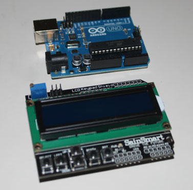
Fig. 2 On top is the Uno flavor of the Arduino ($5 on Ebay), and below is a SainSmart display and keyboard shield ($8 or so on Ebay) that just plugs into the headers on top of the Uno. From now on in these pictures, the Uno will be hidden under the display board. The computer needs to talk to a stepper motor driver, since the computer cannot directly switch the power needed by the motor. Also, a good driver can provide more sophisticated features, like current control and microstepping. A regular stepper typically moves in steps of 1.8 degrees, or 200 steps per revolution. A microstepper driver can increase this by 2, 4, 8 or even 16 divisions. Microstepping at 8 divisions provides 1600 steps per revolution, or 0.225 degrees per step. However, with the kind of stepper motor commonly used, there is a +-5% error in the position, which means that anything more than 10 microsteps per full step is beyond what the motor can deliver anyway. Microstepping makes the motor's motion smoother, but does little to help in terms of accuracy.
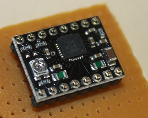
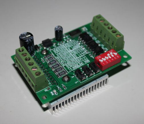
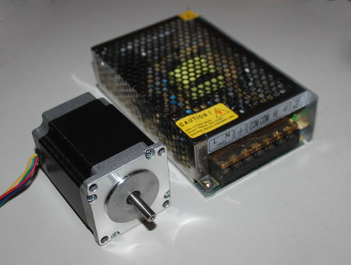
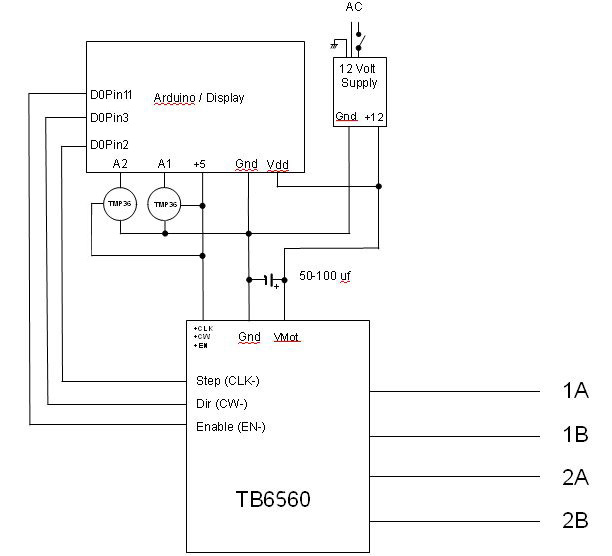
The first thing I tried was a Pololu A4988 Black Edition stepper motor driver I got from Pololu for $16.95 plus 4.95 shipping, shown in Figure 3. However, although it is rated at 2 amps, its current carrying capacity was just too small for the motor I want to use - even with it adjusted for max current it just shut down as soon as I tried to step the motor. The next thing I tried was also from Sainsmart - a biploar driver based on the Toshiba TB6560 chip that should handle the 2 amps of the motor I want to use. It was less money - $7, and is shown in Figure 4. The Toshiba chip is a chopper style PWM driver with the H bridge internal to the chip, so it needs to be heatsinked, and this board has a healthy heatsink. It also provides current limiting, up to16 division microstepping, and has pretty simple wiring with screw connectors. Even though it is not a great driver, we don't really care much about speed or torque in this application so it should perform well for this application. One other thing about this board - the Step, Direction, and Enable signals are provided as your choice of common anode, or common cathode. The CW+ and CW- inputs are wired with +5 routed to CW+ and the Direction signal from the Arduino (DO pin 3 in my case) is sent to CW-. Likewise, +5 to CLK+, Arduino Step signal (DO pin 2) to CLK-, and +5 to Enable+ and Arduino Enable (DO pin 11 - oddly, it is right next to DO pin3 on the shield) to Enable-. Other than that, the on-board switches to select the microstepping values (I set it to 8) and current features are nice. Also, the heatsink provides plenty of convenient places to put the temp sensor. Fig. 5 Figure 5 shows the stepper - a four wire, bipolar NEMA 23 motor with 2.0 amp per coil and 16.2 mh inductance that I got from Circuit Specialists for $23.89 + $11 shipping. It has a holding torque of 24 kg-cm, or 333 oz-inches. Also, a 12V 5a regulated power supply was bought off ebay for $14.90, shipping included. I will also add a couple of TMP36 temp sensors to monitor the temperature of the stepper motor, as well as the heatsink on the driver. They only cost a couple of bucks, and they are easy to interface to the Arduino because it has the A to D converters already built in. Those are just about all the parts needed for the motor control, making this device a stand-alone unit that can be shared between my CNC table, my mill, or any other cutting or grinding fixture I might want to use. Cost for the above is 5 + 8 + 7 + 34.89 + 14.90 = $69.79. I made up a schematic shown in Figure 6.
Fig. 6 Note: If you want to see any of the images on this website in a larger format, you can. If you are using Firefox or Internet Explorer, right-click on the image and select "view image..." If you are using Chrome, right-click on it and "open image in new tab..." After hooking up the Uno's USB port to my desktop PC, programming can begin on the PC and then downloaded into the Uno to test it. The program in this device needs to get the number of divisions of the circle desired from the user. This will be the number of the sides to be machined, or the number of the teeth to be cut on the gear. Then the number of steps needed to go to the next position is calculated. Then, the direction to rotate the material is needed from the user. Since the keyboard has up/down and right/left arrows, it makes obvious sense to use the up/down keys to increase/decrease the number of divisions, and use the right/left keys to rotate the material right/left or clockwise/counterclockwise. This is much easier to show than explain, so further down is a video showing how the components are connected and how I've programmed the user interface.
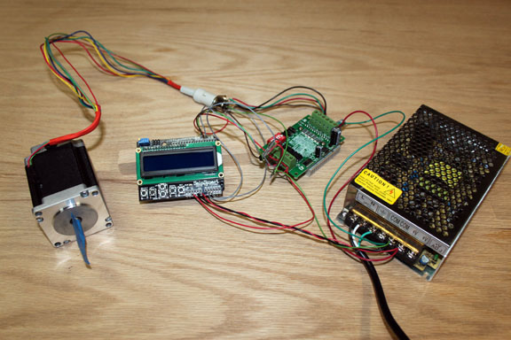
Fig. 7 Above shows the wiring. The current draw is an important detail with steppers since they draw their maximum power when stationary, not at full speed like a regular induction motor. I decided to run the seven wires to the stepper (the four shielded stepper coil wires and +5v, Gnd, and sense for the TMP36) through a connector, allowing the electronics to disconnected from the mechanical part. HOWEVER - if you use a connector like this, just make sure you do not unplug the stepper while it is under power - the energy stored in the stepper's rather strong magnetic field will collapse and need to go somewhere, allowing Murphy's Law to take over and maximize the damage! The Sainsmart display board is pretty simple to get up and running (it just plugs on top of the Uno), but having used it a bit, those tiny switches make it very hard to mount in a project box. If I substitute some panel mount switches, I might have just gone with a 16x2 display and some switches to begin with. Here is a short video showing how the user interface works on the Step Indexer 2.1.
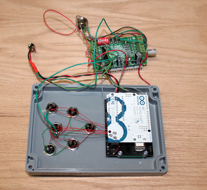
One problem with the inexpensive display sheild is the small switches used - my fingers came in a different size. I brought out leads from the switches to some larger ones and mounted them on the lid of a project box, as well as the display unit. I also added a jack for the power, and mounted the DIN connector to the stepper on the side of the box, shown on the right. On the other side is a hole to be able to insert a USB cable into the Uno to allow programming updates. Before closing up the box, I placed some sized and cut shipping foam around and between the boards to keep them apart and stationary. (Actually, they offer a plan for a box to house a display like this on Thingiverse - if you know someone with a 3D printer you can have them size it appropriately and print it or take the design to Shapeways and they will do it for you. This project was written as an article and published by Digital Machinst magazine in the Winter 2013 issue, and the arduino software is available for download at their website here. When you go that page, scroll down to the Winter 2013 issue, and click the link called "DM8.4 Liming" and the download should commence.
And here is a short video showing version 2.2. There is a new version of the download zip file for 2.2 on the Digital Machinist website that includes a readme file and some more information about wiring, etc. September, 2014 Ok, one of the DM readers emailed me that his machine's fixture had 4.5:1 gear ratio. Oops. The issue is that I wrongly assumed that the denominator of all gear ratios would be 1. In version 2.3, I added the ability to define the denominator of each ratio entered, and displayed that ratio in the splash screen as well as in the ratio mode. This lets you enter a ratio of 9:2, which is the same as 4.5:1. Also, He informed me that not everyone is fond of Fahrenheit (he was from Sweden), so I added the ability to select at compile time either Fahrenheit or Celsius. These are pretty straightforward changes, so I don't think I'll need to do a video for this update. The update is aviailable on the Digital Machinist website. One other comment - there have been a few people that downloaded the code and asked about using unsigned long integers to represent the steps, one even called it "crude" and went off to implement the code in floating point numbers. The reality is that no matter how the calculations are done, and no matter if they are represented as integers, floating point numbers, or cuneiform, the end result must always be an integer number of pulses sent to the stepper, since pulses are all it is capable of using. (Microstepping is not an answer here.) If the division numbers can be evenly divided into the total number of steps per revolution, then life is good. However, when the division number has remainders that could represent fractions of a step you have an issue. However, the only solution to the problem is that as long as the remainders are smaller than the error tolerance you need for the part, then by definition, you don't care about them. If you are going to want to make gears with the number of teeth being a large prime number, then you are simply going to have to use a very high gear ratio for the mechanical front end that matches the resulting tolerance, regardless of how the number of steps are calculated. The way I wrote it allows for the number of steps to be as large as 4,294,967,295 which I don't think of as crude. If you have a need for dividing your circle into more than 4 billion segments, please send me an email about how you are measuring tolerances like that - I would be really interested! Also, some StepIndex builders have reported the keypress values not working on their units. There are now many makers of various 1602 LCD keypad shields, and some use 10% (or worse) tolerane resistors. This changes the values of the keypresses seen by the Uno's A/D converters. To mitigate this, I've written a simple program, the Keypress program, which you can download here. This program loads into the Uno, expecting only the sheild in place, and shows the values for each key on the keypad (other than the reset key.) Instructions for using the program are included in the zip file. Part 2 - Work Fixture For the work fixture, we need a spindle that will turn from a timing belt off of the stepper motor, and a way to affix the gear blank on the other end of it in such a way that the teeth of the gear blank can be cut. The gear blank is usually mounted with a collet chuck, because it provides some versatility about the size of the arbor used to hold the blank. Making a collet spindle can be done in a number of ways. I'll run down several, in increasing order of cost, and you can decide which trade-offs are best for you. The most inexpensive method suggested by a friend was to sacrifice a cheap air grinder to use as the spindle, like this one for $14.99 - 20%. This has a simple fixed 1/4 inch collet on the end and the spindle is removable, but I couldn't figure out a simple way to attach a gear to it. The next cheapest way would be to simply get a 1/2 inch steel shaft, thread the end 1/2-20 to match a drill chuck (HF sells a Jacob chuck for $9.99 - 20%) and get some 1/2 bearings. This would give you a chuck spindle for under $20. You would still have to come up with bearing holders attached to a mounting plate. However, I doubt the runout (how truly round the work would turn in the chuck) would be acceptable with this approach. If the blank showed significant movement as it turned in the spindle, the corresponding teeth on the gear would duplicate this movement, and that would be a pretty lousy gear. Runout would suffer from the inaccuracy of your threading job on the shaft, as well as the inherent inaccuracy of a Jacobs type chuck.
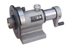
Fig. 10 Another approach is to modify a device made for the purpose shown above - this is referred to as a "spin indexer" and has a 5C collet mount on the left - you would need to get a 5C collet, or a set of them to hold the work arbor. The holed plate might have to be removed for the cutting action to clear the work, depending on how far the work is held away from the collet. Also, you would need to figure out how to attach a gear on the right side where the crank is. The advantages are acceptable runout, a locking thumbscrew, a mounting plate (although you might have to cut some slots on the base) and it can be had for $50-$80 dollars.
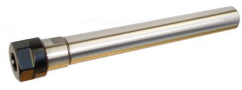
Fig. 11 I found a fairly inexpensive approach but yet retains accurate runout specs, shown in Figure 9. This is a ER16 collet chuck on a straight 1/2 inch shaft, from the ebay seller CTC tools for $17.25. You would need to add a collet for whatever sized gear arbor you wanted, like a 1/4 inch. A whole set of them are around $40, but you only need to get one size that will work for you. The ER16 size will hold collets up to a 3/8 bore - if you need to accommodate a larger arbor, you might want to look at an ER25 or larger. Of course, these larger collets would also need larger bearings, and a larger housing for them, which drives up the cost. The only downside to using this is that CTC tools is in Hong Kong, and you have to wait about three weeks for it to get here - I will get the rest of the mechanical parts and finish the electronics part described above while waiting for it to arrive. Now, the problem is to mount the shaft on some bearings. Since the shaft only needs to rotate to position and rigidly hold it there, all of the problems of high speed bearings are eliminated. The cutting forces are mostly along the line of the main axis, but as long as light cuts are taken, standard bearings should hold up just fine. I decided to use some simple self-aligning pillow blocks, since the low profile of them will allow a greater range of gear blank sizes.
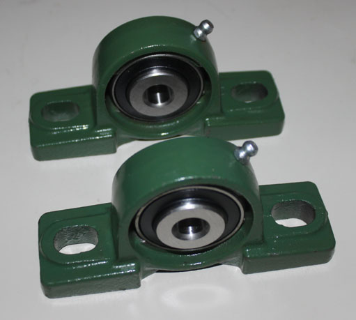
Fig. 12 I found the ones in Figure 12 on ebay for $9.95 apiece, including the bearings and the shipping. I don't like those really large mounting holes on the feet, though - the hole is 1/2 by 3/4 inch.
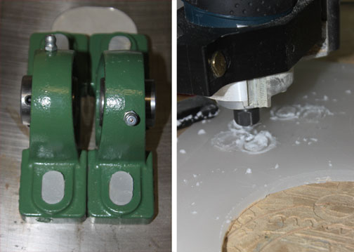
Fig. 13 Above shows the CNC router on the right cutting some kitchen cutting board material into inserts for the large mounting holes of the pillow blocks, shown on the left. Slightly oversize, they were pressed into place. These will be drilled to size to accommodate the mounting bolts.
Fig. 14 Shown above are the timing belt (60 tooth XL style in kevlar) for $6.12, a 30 tooth XL pulley with a 1/2 inch bore to fit the ER shaft for $16.03, and a 10 tooth XL pulley with a 1/4 inch bore to fit the stepper shaft for $10.34, all from SDP/SI. The 30 tooth and 10 tooth pulleys give me a 3:1 ratio, so with the 8 microstepped motor at 1600 steps per revolution, I will now have 4800 steps per revolution, or .075 degrees per step. Seven hundredths of a degree per step is pretty good - on a 2 inch radius gear for instance, one of these .075 degree steps would move just .0026 inches around the perimeter. That's just as well since I figure I pretty much have about a "one-thou" shop. Any more precision would be a huge step up in equipment expense, and especially measurement tools to be able to see the difference. I consider myself pretty lucky to get things to the nearest thou, so that is close enough to target. These may be the last timing gears I will need to buy! What of you wanted better precision? Choose a higher gear ratio - a rotary table typically has a 90:1 ratio, which would make the accuracy be much greater than my 3:1 ratio! There are also steppers with a gearhead on them that would also increase the accuracy beyond what most of us could measure. The above pulley and belt combination means the distance between the centers of the pulleys is 3.9486 inches (the SDP/SI website has a nice little calculator to tell you this), which tells me how close to place the stepper to the mounted ER shaft. Also, I updated the Arduino code to reflect the 4800 steps per revolution number so it will do the math correctly.
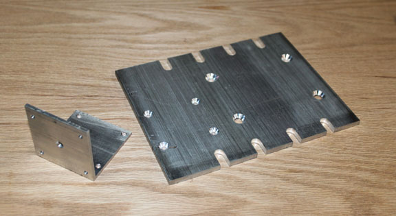
Fig. 15 Above shows two mounting fixtures - one is just a 6x8 by 1/2 inch plate with some side slots cut in it that will fit my mill table, and one is a simple L bracket with a NEMA 24 hole pattern to mount the stepper. Since the rotation of the stepper and the collet shaft needs very little torque, this simple four bolt mount should be rigid enough.
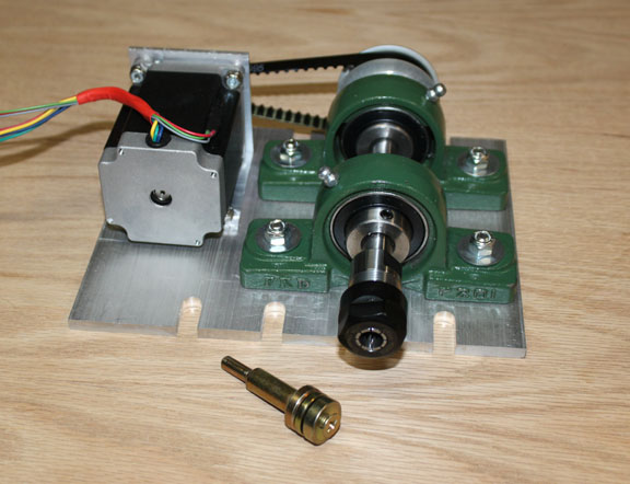
Fig. 14 Above shows the parts for the drive fixture together. When the above fixture is bolted onto my mill table, and plugged into the control unit of Fig. 7, a blank gear mounted in the collet will turn at precise amounts under the milling bit. In front of the unit is a simple arbor for mounting a gear blank with either a 1/4 or 3/8 center that fits either a 1/4 (6mm) or 3/8 (10mm) collet, for $1.99 when they are on sale. This represents all of the major parts of the work fixture, not counting some junk box material for the base plate and the stepper mounting plate. So, total for the work fixture is 32.49 + 19.90 + 17.25 = $69.64. Therefore, total for the project, both the work fixture and the drive electronics, is 69.79 + 69.64 = $139.43 Comments may be directed to gary at liming daught org. Thanks for viewing this build log! |
|||||||||