|
|
Gilbert |
||||||||||||||||||
|
|
October, 2013: One of the tenets of the Reprap community is the idea that these machines could make themselves - well, kind of. You still need many metal and electrical parts to build any of the reprap designs. In reprap lingo, the non-replicated parts are called vitamins. Much of reprap lingo is taken from biology - most of the printer designs are named after evolutionary biologists, like Darwin, Huxley, Mendel, etc. - taken after the idea that biological life is self-replicating and evolving. I guess the term vitamin is taken after the idea that some vitamins are not replicated by the body, but are needed from the environment. Most of the designs, however, are still over 50% vitamins, including the heart of the machine - the microprocessor and control board running the software. I think we are also a long way off from being able to print a stepper motor, but I could well be wrong about that someday. How one got started in this endeavor was to build a repstrap machine (a portmanteau of "reprap" and "bootstrap") which, according to their website, is "a 3D printer cobbled together from whatever parts you can find, which will eventually allow you to print the parts for a reprap machine." When you are starting out, this is a kind of chicken or egg problem - you need a machine to make one, but you are making one because you don't have a machine. It is a frustrating kind of circular reasoning, like when your wife asks you what you are going to do with it when you are done and you reply, "well, make more parts for the machine" and she then walks away, shaking her head and muttering to herself. I can appreciate a design that uses simple, commonly available tools in order to make it, but that is not the case for me. I have a modded metal mill and a CNC router table, so I can entertain a design that utilizes the ability of those, and one that will be the final build, not just something temporary to be replaced with the plastic. It just seems like a lot of work the other way. What I want is kind of like the alla prima method of oil painting - no re-working the brush strokes, just get it right the first time. So, I am going to survey machine designs looking for ones that lend themselves to using a CNC to make most of the fittings. Perhaps I should call this build the "Vitamax" - naahh - that sounds too much like a kitchen juicer. There are printer designs that are driven by a PC, like CNC tables, and there are designs that use a dedicated microcomputer board. Since I have some familiarity with using and programming some microcomputers (here is an example), the idea of NOT having to provide and maintain yet another PC to drive this thing is pretty appealing, so I want to go with one of the those. Also, since this area is developing quickly, a machine that I can build, modify, and adapt sounds more like my style - of course, you might decide differently. If you are eager to be printing parts and do not enjoy the build process, you might be better off just buying a ready 3D printer kit. Looking around at some of the machines, they all look a bit small to me, with a 6 or 8 inch cube for a build volume being normal. This sets the size of the largest object you can make in one piece, although you can make them fit together to form larger ones. I would like something more like 12 by 12 by 12, a nice round cubic foot. In order to print with some kind of plastic, like ABS, the base platform to print on must be heated or the part might warp, so having a heater of this size also constrains the size a bit. I decided to start with the computer and electronic side of things first, working my way out to the motors and bearings. After a lot of reading, I decided to go with the open source RAMPS 1.4 using a Mega 2560 Arduino microprocessor clone running the Marlin code base. (RAMPS is an acronym for Reprap Arduino Mega Pololu Sheild.)
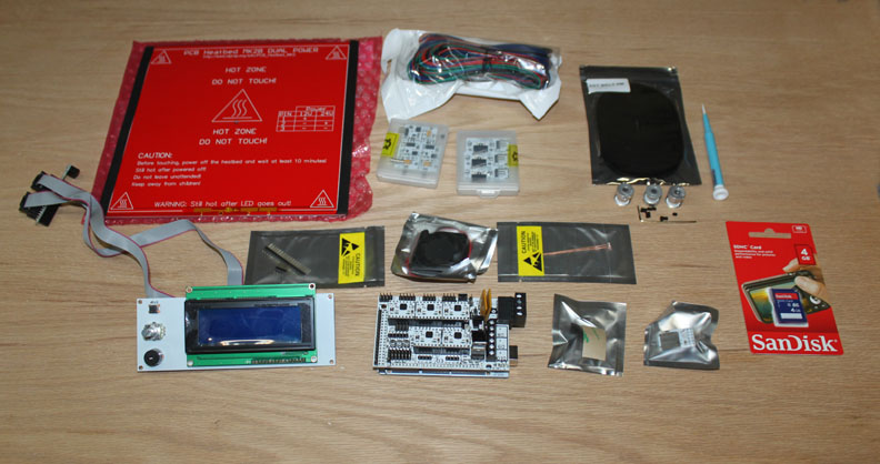
Fig. 1 Figure 1 shows the result of an order for a "multivitamin" I placed on Ebay (seller was reprapdiscount), and what I received just 45 hours later. The package came from Hong Kong, and shipping was $15. I am pretty familiar with the aviation industry, but I still find this to be a modern wonder - what would you say if someone handed you a box and said "You've got less than 2 days to take this to China - and oh yeah, here's fifteen dollars to cover your expenses!" It costs me three times that just for a cab ride to my local airport! There are several reasons I picked this particular RAMPS package, but the main one is that this particular Arduino clone (called a "Taurino") has the ability to run on 24 volts. Since there are heaters and stepper motors involved, higher voltages will be more efficient, but other Arduinos only go up to 12 volts. Plus, I already have a 24v supply. Hopefully, this one is also compatible the the Marlin code base I want to use. The other big reason it that it includes an SD card interface, supported by Marlin, so the machine will run stand-alone. You copy the g-code file onto the SD card from your design computer, and slide it into the SD slot, and the machine runs from there. In top left of Figure 1, the big red board is the heater base. It is a MK2B, which is only 8x8 inches (actually, 210mm x 210mm - this is going to be a metric animal) and is simply a PC board with a trace pattern on the back used as a resistor to get some measure of even heating. The B indicates there are two connections, one for 12 volts, and one for 24. I will probably swap this out for a larger one later. To the right is a wiring bundle with Arduino type header connectors. Under that are containers for both the Hall effect limit sensors, as well as the microswitch type limit sensors. To the right of those is some GT2 timing belt, and three GT2 pulleys to match a NEMA17 stepper shaft, and some set screws and hex wrench to go with them. They also threw in a tiny screwdriver. On the left, the display with the ribbon cable is the smart LCD controller, compatible with the open source Marlin software that allows status information and menus to be displayed and selected. It also accommodates an SD card socket, and the package even included a 4 gig SD card shown on the right. Above it are some header pins, with a small 40x40mm fan and the heater board thermistor on the right. Below those is the main RAMPS 1.4 shield already populated with the A4988 Pololu stepper drivers, and the Arduino is already mated under it. To the right are the heat sinks for the stepper drivers, and the SD card adapter. The unit arrived with controller software already loaded on it, but the first thing you need to do is install the Arduino IDE, the serial to USB driver on your computer, and get the Marlin source, compile it, and load into the Arduino since you will have to modify some of the parameters to fit your printer's specs. If you plug the LCD card into the Arduino with its shield on just as it ships, and plug the unit into your computer's USB, the USB can power the unit enough to load an run the Marlin software. However, an external supply will be need to power any steppers or heaters.
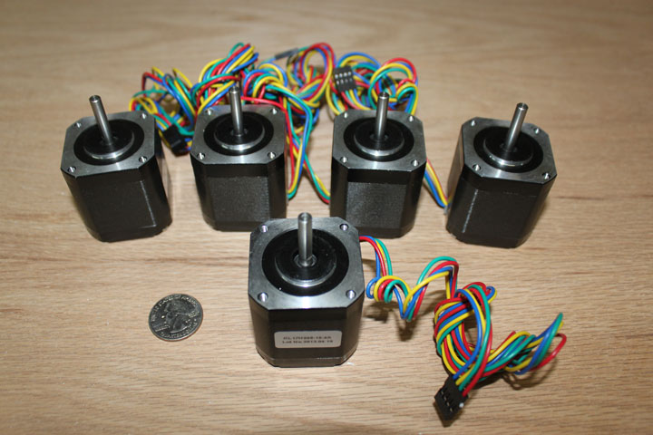
Fig. 2 The Mendel type printer needs 5 steppers - one for X and Y axes, two for the Z, and one for the extruder. You can use a variety of stepper motors on these things, but the sweet spot seems to be the NEMA 17 size, shown above next to a quarter. The ones above are KL17H248-15-4A with a 1.5amp current per phase, holding torque of 5.5Kg.cm (76 oz-in) and an inductance per phase of 4.8mH and a shaft of 5mm. These are a little on the beefier side for a 3D printer, so it should give me some room to select various linear slide methods if I want to upgrade. These machines are different from CNC mills in that there is very little force involved in positioning the extruder. On a CNC milling machine, rigidity is everything. On these machines, light weight to support rapid movement using small steppers is more like it. One design in particular I looked at was the OB1.4 design by Simon Holmes (wired1 in New Zealand) that calls for the use of Openbeam type aluminum extrusions. However, a cheaper alternative is the 15mm x 15mm Misumi extrusion, whose use for this is well demonstrated by Hossmachine's Dan Kemp. The design seems to lend itself to machine the beam connectors out of aluminum. The key to making these is to be able to accurately position the holes, which my CNC and my DRO'ed mill does very well.
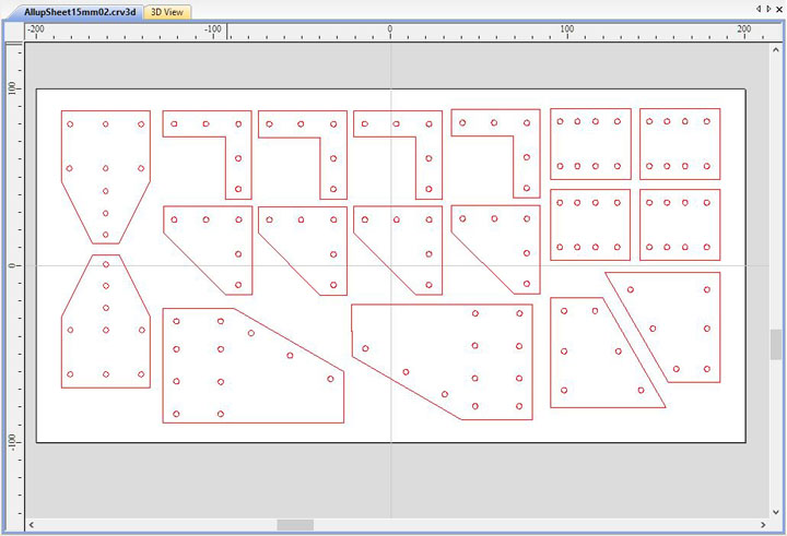
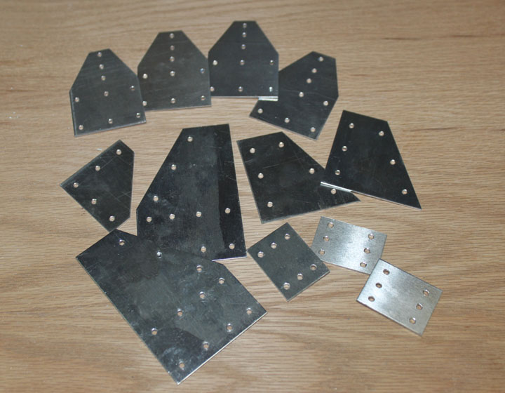
Above in Figure 3 is a design layout sheet for many of the connector plates to fit the 15mm Misumi extrusion, to be drilled out on the CNC or DRO'ed on the mill. On the right are some of those connectors, milled out of some 6061-T6 aluminum .062 thick. What is important here about the plates is not the outside accuracy or shape of the pieces, but proper alignment and spacing of the 3mm holes, which my mill did very quickly using the DROs, and I cut most of the edges with a sheet metal shear and smoothed their edges with a swipe of a deburring tool.
These plates definitely remind me of an Erector Set I had many, many years ago just like the one shown on the left! (or, perhaps, a "Meccano" to my friends in the U.K.) I'm going to call this design the "Gilbert", after A.C. Gilbert, shown in Figure 6, who invented the Erector Set. He may not have been a biologist, but he did inspire countless engineers and scientists - the A.C. Gilbert Co. also sold thousands of chemistry sets, like the one in Figure 7, that introduced so many kids into the mysteries of litmus paper, crystal growing, gunpowder, etc. I'm betting some of them even became evolutionary biologists!
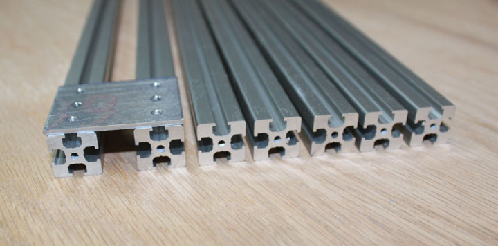
Fig. 8 Above shows some lengths of the 15x15mm Misumi extrusion, part number HFS3-1515. This stuff is quite reasonable - only $10.30 for 2 meters of it out of Chicago. The center hole can be tapped for 3 mm threads (its 2.5mm in diameter), but having a 4-40 tap and bolts on hand, they worked as well - there is only a .009 in. difference in the drill hole size. Just make sure you use an appropriate tapping fluid for aluminum and keep the tap straight. (Now, if they had just perfected a way to extrude threaded holes, I would have been really impressed!) The plate shown above on the left (two rows 25mm apart of three evenly spaced holes) is used to create the sides, which are two extrusions 10mm apart to allow the 10mm linear motion rods to pass through. The main thing is that after you slide the 3mm nut into the track, there isn't much clearance for the threads on the far side of the nut - you don't want the bolt to bottom out into the track - so you have to pick the length of the bolt with care.
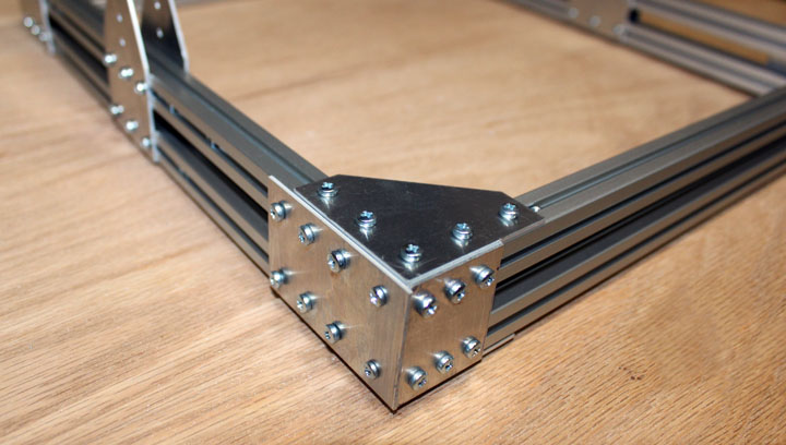
Fig. 9 Above shows the corner of the base being made from the extrusion and the plates that were made in Figure 4. This forms a very rigid structure, as the nuts seem to "dig in" when tightened, but once this design is complete, I will go over everything with some temporary (blue) Locktite threadlocker. One could argue that three bolts to secure a plate to an extrusion might be one too many, but they are very cheap and easy to use. As the saying goes, "two points make a line, but three points confirm a line." Almost all of the bolts in Figure 9 are 6mm in length - you need a couple of hundred of those. Don't even think about getting the bolts and nuts at a big box store - you can get 100 of these 3mm nuts for $1.39 (McMaster Carr # 90591A121) and 100 bolts are a whopping $2.56 (McMaster Carr #92005A116) but if you want to spend more money for a more "machine like" look, you could get some cap head bolts instead, but a hex wrench only makes it easier to strip the tiny 3mm threads. I got a few other lengths of bolts as well to accommodate thicker pieces. When assembling, I found it was at times much easier to insert all the bolts into the plate and turn the nuts on just far enough to fill the nut with threads. Then, the plate can be slid onto the extrusion while jiggling the extrusion a bit to allow the nuts to enter the tracks. Other times, it was better to slide the nuts in the track, position them under the holes of the plate, and then bolt the plate on. In the tracks above you can see some "spare" nuts in the track so that I can make attachments in the future without having to take the frame apart. The two slightly smaller bolts on the corner are the 4-40 bolts whose threads go into the ends of the front extrusions. All the rest are 3mm bolts and nuts. Assembling this thing brought back memories of Christmas morning!
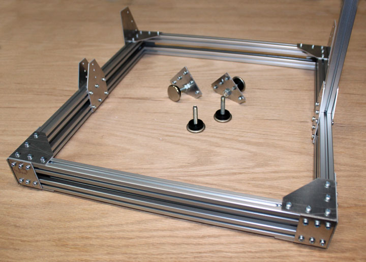
Fig. 10 Here is the base with upright plates for the X and Z axes. (It seems a convention that on Mendel or cartesian type reprap machines, front-to-back is the Y axis, left-to-right is the X axis, and up-and-down is the Z axis.) All the extrusions above are 360mm long - the size inside the base is 360mm x 325mm (about 14 x 12.75 inches, well within my 1 cubic foot print volume goal.) I thought about making some leveling feet from four flat head bolts and cutting board plastic, but I saw the feet shown in the middle of Figure 10 while at a big box store (Lowe's, I think) and for $2.50, the problem was solved.
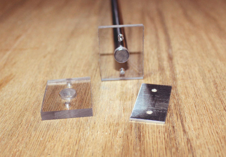
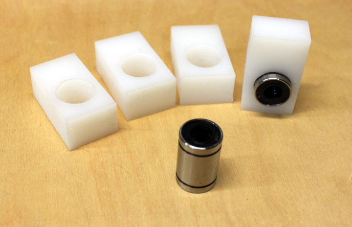
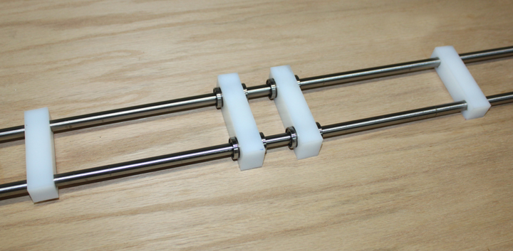
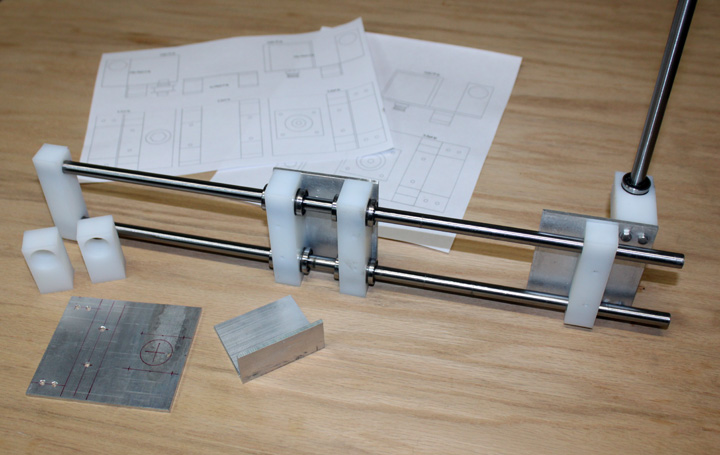
Figure 11 shows some 1/4 in thick clear Lexan (polycarbonate) linear rod holding brackets drilled out to the 10mm diameter of the O1 tool steel rod (McMaster #88625K69) and a matching aluminum cover. The covers keep the rods from sliding out of their brackets during table movement. Figure 12 shows the LM10UU (10 for $8.99 +$3.50 shipping on Ebay) linear bearings that fit onto the 10mm rod in Figure 11. I've cut some UHMW polyethylene to cause a press fit for the bearings. If there is ever any slippage, I can just add some snap rings because the plastic is .75 in thick, the same distance between the snap ring grooves on the bearings. They fit very tight for now, though, as I had to press them in place with a vise. These standoffs will be drilled and threaded on top for mounting screws to attach the base table to the linear rods.
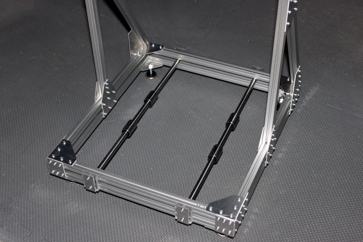
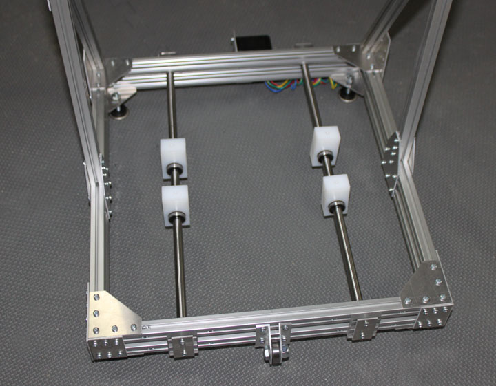
Fig. 13 Above shows the base with the feet on, the uprights in place, and the Y axis tool steel rods mounted with the end brackets of Figure 11, also with the linear bearings slid in place. All this all forms a very rigid base for the machine.
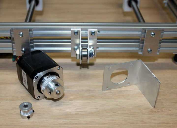
Fig. 14 Above far left shows one of the GT2 20 tooth timing pulleys that came with the RAMPS kit, but its diameter is too small to span the 15mmm extrusion, so a 36 tooth GT2 pulley will be used, shown mounted on the stepper motor. In the Repetier software you must specify the number of steps needed to move 1 mm for each axis, so changing this gear size will alter that number. Thoughtfully, there is a nice calculator built into Repetier that does this for you - you type in the degrees per step of the motor (1.8 in my case), the microsteps (8 in my case), the belt pitch (2mm for this GT2 gear) and the number of teeth (36) and presto, you get 22.2222 for the number of steps per millimeter. The 20 tooth gear has 40.0 for this value. A motor mount bracket was made from 1.5 inch aluminum angle, shown on the right, that follows the 31mm square bolt pattern of the NEMA 17 standard. Mounted in the middle are two brackets cut from the same angle stock for a 5/16 bolt to hold the ball bearing that serves as the Y axis belt idler. The motor will mounted on the rear such that the center of the motor axis and the center of the idler axis line up with the center of the lower extrusion, allowing the belt to go around the front and rear extrusions.
Fig. 15 Above the Y axis is nearly complete - the white bearing holders have been tapped to attach the table base, and the Y stepper is mounted in the rear with the Y idler mounted on the front. The belt will wrap around the stepper pulley, go under the base, around the idler bearing, and pass between the extrusions to be attached to the base of the table.
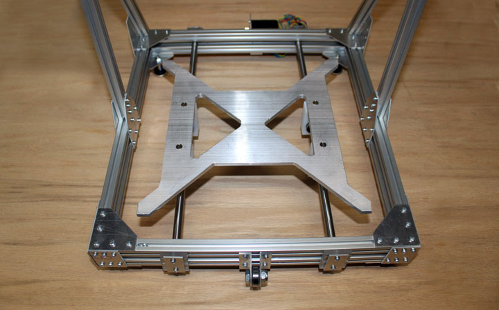
Fig. 16 I milled a solid base from .25 thick 6061-T6 that rides smoothly on the linear bearings. It weighs less than 15 ounces, so it should accelerate very easily. On top of this will ride the MK2B heated base in Figure 2, mounted on height adjustable legs, and a glass surface on top of that which is where the printing will occur. Now, all that is left for the Y axis is to attach the timing belt to the base and mount the heated bed and glass.
Fig. 18 The X axis is constructed like the Y using the same materials - UHMW polyethylene is drilled to accommodate the rails and bearings at a constant distance apart. These can then be screwed onto mounting plates.
Fig. 19 Above is the initial X-axis design with mounting plates and Z bearings being attached. I did make up some drawings to help while cutting and drilling. The end plates are horizontally symmetric, so you can place the stepper on either the right or left of the base. After makng the fixture on the right, though, I realized I could make it smaller by using the space between the rods to house the idler pulley.
Fig. 20 Above, I've redesigned the mounting plate for the right and left X-axis. This makes it smaller and a bit lighter. The idler bearing has two C rings to separate it from the washers that act as a belt guide. I used a 1.5 inch 5/16 bolt (along with the washers and nylok nut) because that fit the bearing I had on hand, but a smaller bearing and bolt would probably work better. I also needed a spacer to position the bearing further out from the rods, so I used some 1/2 inch PEX pipe I had, but copper pipe, wood, or just about anything could be used here. Barely visible is the thin plate on the far right that forms a stop for the rod ends. The left mounting plate is the same only turned over, except that instead of an idler bearing assembly, there is another plate attached to the front piece of UHMW to hold the stepper motor.
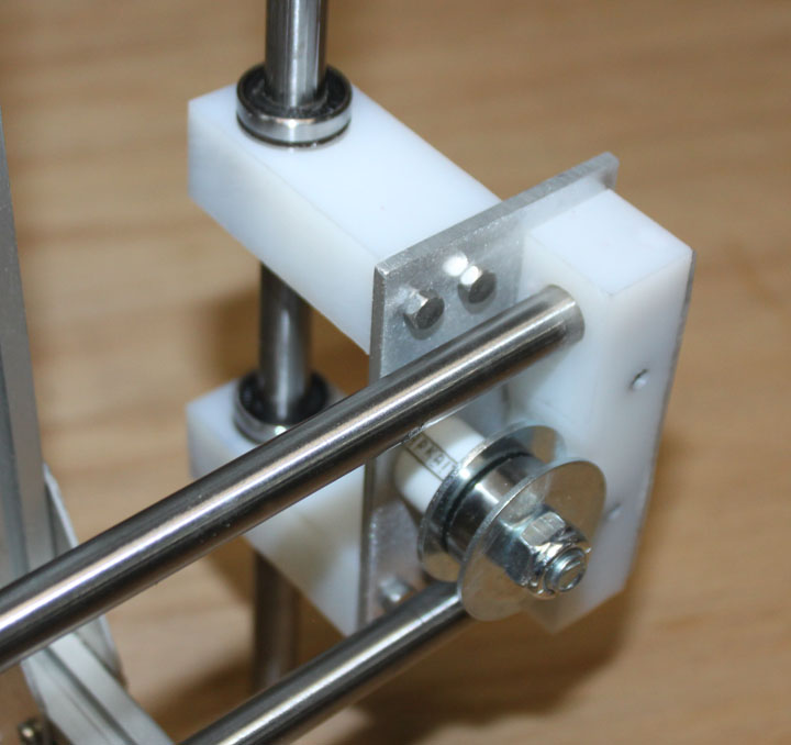
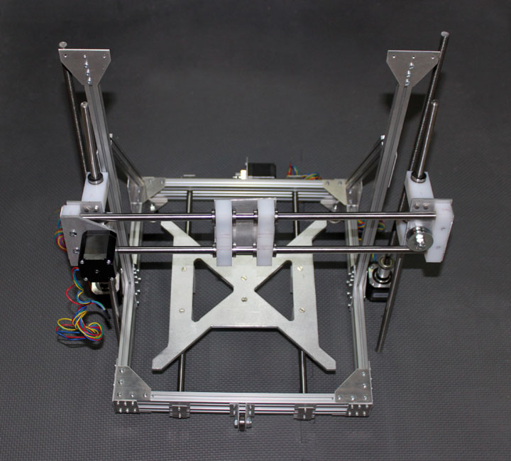
Fig. 21 Here you can see what the three axes are all about. The X axis stepper on the left will drive a belt that is connected to the carriage held at the middle of the two horizontal linear rods, moving it right-to-left. The entire X axis (the same two rods and everything connected to them) will then move up and down on the vertical linear rods (the Z axis) driven by twin acme screw rods, attached to the steppers that for now are simply resting on the ground. As before, the print platform moves front to back by the Y stepper at the rear. The X and Z rods are still a little too long, but I will wait to see where to cut them and then the belts will be fitted to that length. The X carriage needs to be positioned over the center of the base - this will allow the nozzle to work over the full travel of the print platform. The heavy parts of the X axis are the 10mm rods and the stepper motor, but I would hesitate to use a smaller rod, lest the carriage sag. However, the impact of this weight is minimized by the fact the Z only increases slowly during a print, and has two steppers to move it. I may later add some lightening holes to the carriage plate, if there is room for some, since it will be in constant motion along with the print bed.
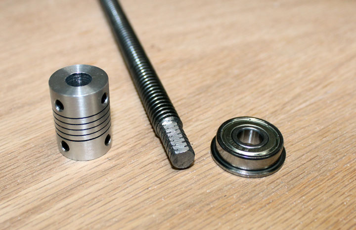
Fig. 22 Figure 22 shows the end of one of two 3/8 Acme threaded rod that I turned down on a lathe to 8mm. These threaded rods will be used to raise and lower the Z axis. I chose Acme rod because I have had poor luck with the allthread rod you get from a big box store. You can make allthread work smoothly by running the whole rod through a die first, but I'd rather just spend a few dollars more for something that's ready to use. Perhaps some stainless steel allthread would work, but then the difference in cost between stainless and Acme is small. (the needed 3 ft of Acme 3/8-12 shown above was $18.97 from McMaster) The shoulder created by turning this down rests into the 8mm flanged bearing shown on the right, which will also serve as a thrust bearing to support the weight of half of the X axis carriage and extruder. Since this is not a lot of weight, a regular roller skate type bearing can serve as a thrust bearing as well. The rest of the rod end goes into the 8mm side of the adapter, shown on the left, whose other 5mm end goes onto the shaft of the Z axis stepper. You don't need to remove much to reduce the rod to 8mm - if you don't have access to a lathe, you could chuck one end of the rod into a drill, and push the other end through the flanged bearing into a hole to hold the bearing in a piece of supported wood, and carefully hold a file across the area to be reduced as the drill spins the rod. In any event, after the end diameter is ready, a flat is created in the turned down area with a file while the rod is stationary to give a place for the set screws of the coupler to land.
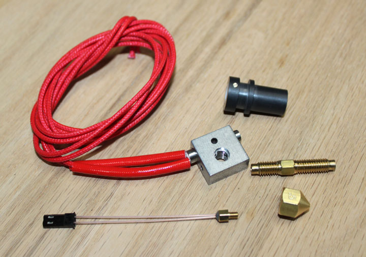
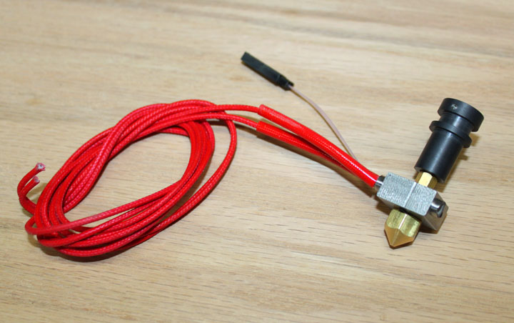
On the left shows the MG Plus J-head hot end, sold by RP One Labs on Ebay, as it came unassembled. It did have the thermistor already glued into its brass fitting, with insulation and a JST connector on the leads, and included a matching female JST for the other end. The heater is for 24v, but make sure you specify 12 or 24 when you order. The black PEET body on the upper right has a Teflon core for 3mm filament, but that can be replaced for 1.75mm filament. The nozzle, lower right, extrudes .5mm, but is easily replaceable with another size or for cleaning - this removable nozzle was one of the main reasons I chose this head. The heater leads also have a heat-tolerant sleeve over them. On the right is the hot end assembled according to the specs, and ready to install on the filament feeder and wire up to the RAMPS board.
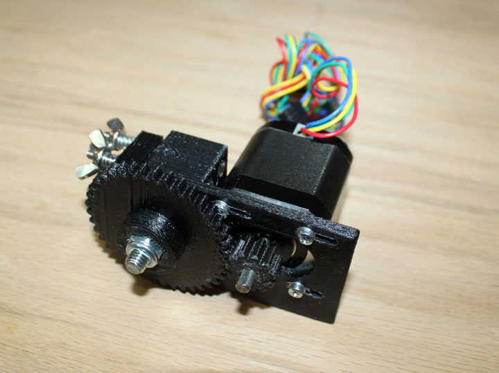
Fig. 25 Above is a filament feeder where the stepper turns the large gear, which turns a toothed bolt that squeezes filament between it and a bearing that presses on it by the springs and wings nuts. The J-head is to be mounted under the feeder, directly under the bolt. The feeder pushes the filament down into the J-head hot end shown in Figure 26, which melts the filament and extrudes it. The design of the feeder is called a Wade's extruder. I don't like this design because it is too wide and restricts the x axis length. It should work long enough to print a different one, though.
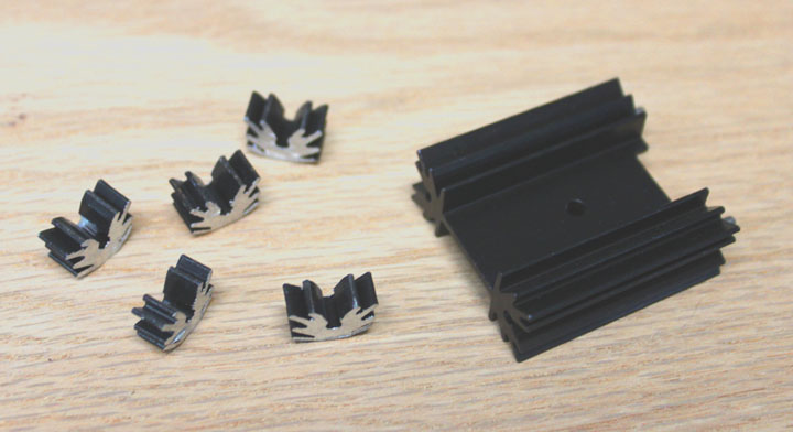
Fig. 26 Above left are some heatsinks I made by cutting up and filing a TO-5 type sink on the right, which I had in my junk box. These will be thermal epoxied onto the stepper driver chips to add some thermal mass to them. I am not sure if I need them at this point, but I am trying to avoid the need for a fan over this board, and its a lot easier to put them on now. This is as far as I got before being seduced into the delta configuration. Perhaps it will be finished on another day... Thanks for reading! Comments may be addressed to gary at liming daught org. |